EFD介紹及EFD之實例驗證
勢流科技 資深CAE工程師 杻家慶(Jason Niu)
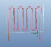
熱設(shè)計 http://m.aji87.cn
Agenda
Introduction of EFD
Key technologies of EFD
Application in EFD
EFD之實例驗證
Introduction of EFD
What is EFD??
EFD指的是Engineering Fluid Dynamics
EFD是一套簡單易學(xué)的熱流分析軟件
對于工程師在CFD分析背景的要求較低
直接將CAD模型導(dǎo)入CFD的概念,使設(shè)計工程師可以在設(shè)計前期找到最佳化的模型
EFD是一套專為改善研發(fā)設(shè)計前端的熱流分析軟件
Typical Development Costs
EFD Product Family
EFD. Lab: 使用solidworks接口
EFD. Pro:使用Pro/ENGINEER接口
EFD.V5: 使用CATIA V5接口
EFD. Flexx:適合使用不同CAD軟件的user,可直接利用floating的方式到不同的CAD接口
Key Technologies of EFD
DC3 –直接將CAD的模型導(dǎo)入CFD的概念
RAM –矩形網(wǎng)格自動生成
MWF –改良邊界層的計算函數(shù)
LTTM –層流漸變到紊流的精確計算模式
ACC –自動收斂控制
DVA –參數(shù)化設(shè)計分析
EUI –工程師使用平臺
Direct CAD to CFD Foundation
直接使用PRO/E、solidworks、CATIA建立模型
自動區(qū)分固體與流體空間
自動檢查內(nèi)流場與外流場區(qū)域,無須在CAD中建立流場區(qū)域
Rectangular Adaptive Meshing
自動對流體與固體區(qū)域劃分網(wǎng)格
自動針對物理特性與外型特征進行網(wǎng)格加密
No “black box” approach亦可利用參數(shù)控制網(wǎng)格的生成Base mesh Refine mesh
Modified Wall Function
接近邊界層的網(wǎng)格采用partial cells技術(shù)定義
物理修正流動與熱傳現(xiàn)象的邊界層效應(yīng)的模擬EFD simulation Experiment
Laminar–Transitional–Turbulent Modelling
采用改良邊界層的計算函數(shù)直接仿真層流與紊流的現(xiàn)象
不須指定流體的特征,即可在同一個模型仿真出由層流 漸變流 紊流的現(xiàn)象
Automatic Convergence Control
使用者可以針對模型選擇某面、某對象、計算域的任何變量作收斂控制
使用者可以針對具代表性的方程式作收斂控制
不須作任何數(shù)值方法的控制即可完成收斂
Design Variant Analysis
采用” what-if ”的設(shè)計概念,直接利用參數(shù)對模型進行優(yōu)化設(shè)計
優(yōu)化模型可直接被CAD采用
Engineering User Interface
Easy-to-use:采用CAD平臺直接進行CAE模擬
Easy-to-learn:以工程師角度設(shè)計,使用工程師語言,讓工程師容易學(xué)習(xí)
深入的結(jié)果解析與圖形顯示功能
直接產(chǎn)生MS-Office格式的報告
These features are available for the Electronics module users only.
Electronic Database
增加電子產(chǎn)品相關(guān)數(shù)據(jù)庫
包含material、Fan curve、Heat pipe、PCB…等
Perforated Plate
可以選定對象的面設(shè)定其為2D Resistance。
設(shè)定其free area ratio與hole shape等
Two-Resistor Component
利用選定Junction與case對象,以及設(shè)定junction 的性質(zhì),即可模擬two-resistor component。
Two-Resistor model Normal model
Electrical Condition
利用設(shè)定current、voltage或contact resistance,模擬焦耳熱功問題。
Heat Pipe
僅須選定heat pipe part,定義加熱端與散熱端,并設(shè)定有效熱阻值(effective thermal resistance),即可模擬熱管。
Printed Circuit Board
PCB(Printed Circuit Board)模塊可以直接設(shè)定PCB各層的銅覆蓋率,更方便且精確模
擬PCB散熱情形。
Application in EFD
Simulation of chip thermal state
Thermal model of a chip
kx=ky=Solder and Air 25*25*0.8 mm3 y=0.034; kz=11.2 W/(m*K)
Substrate 25*25*1.14 mm3 kx=ky=9.9; kz=2.95 W/(m*K)
Bump and Underfill 8*7.3*0.07 mm3 kz=5 W/(m*K)
Die 8*7.3*0.86 mm3 Silicon
Surface heat source: 15 W
In considered tasks ambient temperature was set as 20 ??, gravitation and radiation were taken into account
Chip with heat sink and interconnection simulation
PCB has three layers. Thickness of each layer – 0.5 mm.
Interconnection thickness – 50 microns.
Heat sink [°C] 99
Pcb 1 layer [°C] 44
Bump and Underfill [°C] 103
Solder and Air [°C] 87
Substrate [°C] 88
Die [°C] 103
Number of mesh cells 252,724 Computational time ~ 2.1 h
Thermal Management for Projectors
Natural Convection with Radiation
Heat model of headlight
Screen
Headlight
Lamp with power of 30 W
-The heat radiation from the light source;
-The rays penetration through the transparent
bodies;
-The rays reflection from the reflective surfaces;
- Radiation heat exchange between bodies;
- Natural convection process;
- Heat conductivity in solid bodies.
Model of the headlight
Aluminum Headlight
housing
Bulb and
headlight glass
Volume inside the
lamp
Filament
Parabolic reflective surface
The filament has temperature of 2500 K
The screen is modeled by the low
conductivity material with emissivity of
0.8
Temperature at the screen
Diameter of the hot spot on the
screen corresponds to the
reflector diameter.
There is the temperature tail
which corresponds to the natural
convection flow near the screen
Temperature and convection flow field
Passenger compartment ventilation
Back face
Pressure 1 bar
Inlet
Air velocity 0.5 m/s
Passenger compartment heat transfer task
Housing material – Stainless Steel
Passenger compartment-Result
Satellite exposure to sun radiation
Trajectory
Re= 6300 km
Ro=48000 km
Heat source 1.5 kW
Satellite material – Aluminum
Emissivity coefficient = 0.7
國防工業(yè)
CALCULATION OF F16 AT M=0.6 AND 5o (H~500 m)
建筑業(yè)
建筑流場與太陽輻射分析 機械工業(yè)
壓縮機模擬
控制閥模擬
機械工業(yè)
Water mixer
Heat exchanger
EFD 模擬與實驗比較
感謝不具名的客戶提供
Agenda
前言
實際案例測試
Case 1
Case 2
Case 3 & 4
(Thermal performance prediction of design changed)
前言
熱流數(shù)值仿真于近年來在電子3C產(chǎn)業(yè)之研發(fā)中使用越發(fā)頻繁,如何快速、準(zhǔn)確的預(yù)估是研發(fā)(R&D)工程師首重考慮之部分。而目前市面上各軟件商無不發(fā)展適合工程師使用之熱流數(shù)值仿真軟件。
熱流數(shù)值仿真軟件之選擇,首重于研發(fā)體系中熱流模擬階段所占之重要性,以及即將使用此軟件之工程師共同試用后之評價。
最后先透過兩個舊案進行數(shù)值分析與實驗之比較,了解軟件之功能與實際應(yīng)用之狀況。另外再透過一個開發(fā)中之案件協(xié)助工程進行判斷依客戶要求減輕重量而減少鰭片數(shù)量后對效能之影響,提供快速的結(jié)果比較。另外一探討不同階段模型對于趨勢預(yù)測之影響。
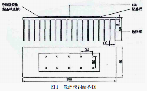
產(chǎn)品實際案例Case 1
PQ-fan
分析的設(shè)定如下:
1.發(fā)熱瓦數(shù)62W
2.環(huán)溫42℃
3.cpu與sink間無建構(gòu)grease
4.風(fēng)扇使用PQ曲線分析所需時間:
1.建構(gòu)與設(shè)定分析模型:
20min (不含3D pro/e檔建構(gòu))
2.求解: 約2hr
3.后處理: 20min
Case 1 simulation result
5% error
產(chǎn)品實際案例Case 2
PQ-fan
分析的設(shè)定如下:
1.發(fā)熱瓦數(shù)115W
2.環(huán)溫35℃
3.cpu與sink間無建構(gòu)grease
4.風(fēng)扇使用PQ曲線分析所需時間:
1.建構(gòu)與設(shè)定分析模型: 40min(不含3D pro/e檔建構(gòu))
2.求解: 約3.5hr
3.后處理: 25min
Case 2 simulation result
4% error
△T ofheat-pipe isabout6 oC
Thermal performance prediction of design
changed
Agenda
Purpose
Thermal Experiment
Simulation result
Discussion
The influence of fan duct
Purpose
Due to the weight of cooler, reduce the fin number to reduce the weight.
Use the thermal fluid analysis tool EFD.PRO to evaluate the temperature difference before mockup .
Software validation test also.
Model drawing
Origin: 112 fins Modified: 84 fins
Thermal Experiment
Thermal test platform and test sample
LGA775 TTV 8025 axialfan Heatsink case 3 & case 4
Assem bly sam ple
Fan duct
Fan cover
Simulation model
Ta=35 oC
CPU Power =65W
Fan =P-Q fan with 4500RPM
Fan (flow) direction is bottom to top Simulation
domain CPU
Simulation result of Model 1 (Origin) Surface plot Temperature section plot Vector plot Temperature section plot
Simulation result of Model 2
(fin number reduced)
Surface plot Temperature section plot Vector plot Temperature section plot Temperature comparison
Section plot of temperature (fix scale)
Temperature difference is about 5oC between two model.
Discussion - Data comparison
The difference between experiment and simulation in absolute value of temperature is about 5oC.
The thermal resistance difference in two heat sink are 1.80
and 1.73 of experiment and simulation. The trend of simulation is cohere with experimental data.
Improvement of model constriction
Add a Fan duct to close the real model
Flow pattern
We can see that the flow pattern is quite different. The hot air will not return into heat sink, the result should be more close to real test.
Simulation result
Surface plot Temperature section plot
Vector plot Temperature section plot
Temperature result
Temperature of the simulation with fan duct is close to experimental data. Temperature of the simulation with fan duct is a little higher than experimental. When add a fan cover, the temperature should lower than experimental.
This result is more reasonable.
Conclusion
配合實驗數(shù)據(jù)的驗證,證明EFD在進行thermal module的模擬時,具有一定的準(zhǔn)確性;加上EFD可以直接將CAD建構(gòu)的模型進行散熱分析,因此對于近來幾何外型有愈來愈復(fù)雜的thermal module而言,不需要做太多的外型簡化,即可仿真,對于增加產(chǎn)品開發(fā)的效益有實質(zhì)的幫助。
FloEFD資料下載: EFD介紹及EFD之實例驗證.pdf
標(biāo)簽: 點擊: 評論: